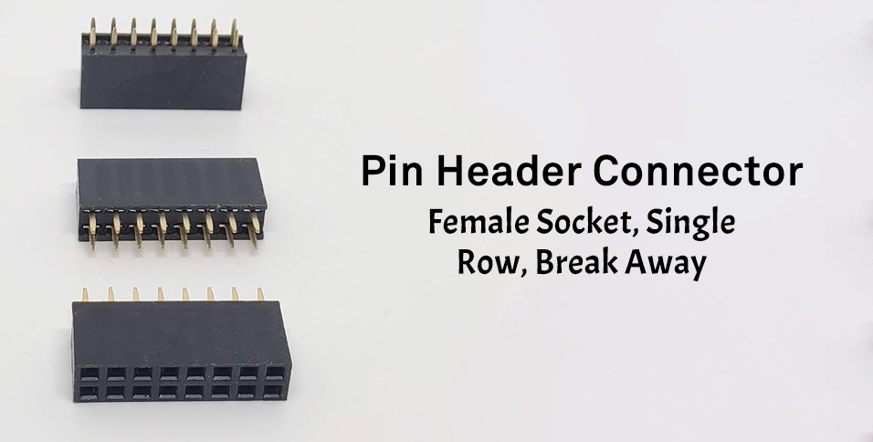
This introductory paragraph presents the female socket pin header connector for a single row, and in break-away format. Welded at an even pitch, the pinned header points communicate better with circuit boards while allowing signals to find the shortest route to the other side, away from risks. It is also supported by provisions found at either end, and is designed for standard spec and profile. Then, engineers love it because, in addition to the various options of soldering, they can also cut in-between to get a specific pin count. However, the headers used in conjunction with such applications must be able to slide into a small clearance. For any other payloads of sensors, microcontrollers, or peripherals controlled by the n-female headers, strong physical retention and flawless electric performance should prove a constant for the modular building of this single-row socket.
For more in-depth information you should view from Female Headers Manufacturer&Supplier – Soulin
Product Overview
The product is a single-row female header, in the form of a socket with a . 1″ pitch that matches the standard footprint found on most pcbs. The connector is based on a modular, breakaway design that allows the header strip to be easily broke into customized lengths without compromising the electrical integrity through all pins. Being designed to mate with connectors and individual pins having generous insertion force while ensuring reliable contact pressure, this brings in a vast field of application areas in electronics. Several typical specs including the overall height, contact plating material, insulation material, current rating and others all to affect the durability, signal quality, and heat concentration. Hence the possibilities for its use arise in supporting quick assembly, easy rework, and reliable interconnections for consumer, industrial, and educational electronics.View Female Headers Manufacturer&Supplier – Soulin for More Details
What is a Pin Header Connector?
The PIN header connector constitutes a modular interconnection system composed of arranged conductive contacts aligned to a particular row and space measuring 0.1, giving it wide electronics versatility for most applications. The female header version, meanwhile, consists of socketing spring contacts which engage male headers or stand-alone pin posts. It provides a secure and reusable connection. Pin headers usually come in both single-row as well as multi-row configurations. The plugging concept together with single-row format is the optimal design for traceability and board area while the break-away design helps to create the desired number of pins, thus reduces inventory headache. This type of product reconciles both mechanical stability, ease of soldering, and electrical performance for prototypes and production printed circuit boards.
Importance of Female Headers in Electronics
Female headers contribute to the modularity and maintainability of circuit designs as well as safe coupling. The shrouded socket prevents the contact being exposed, providing guidance to its mate, accepting aligned insertion, and stems from the rough-use issues that arise from bent pins. Female header connectors are a project standard of 0.1 inches that is universally accepted for use with most any development system and HAT header. These connectors are ideal for design interfaces since the female part would be all gone, opportunity for any configuration, not necessarily custom tool-sized knobs. Moreover, when the female pins are being broken away, this system allows PCBs to support board-to-board stacking and other vertical or horizontal connections that involve a number of insertions again after the initial pair. Female connectors make integrated functions very easy for repeated insertions by way of plug-in-board application programming thereby negating the need for soldering.
The above discussion brings females to the consideration of a solid foundation of current-day boards, centering on the welfare of modularity, reliability, and certain standard regulations!
Use of Single Row Break Apart Connectors
Single row breakaway female headers serve many places using very compact, configurable interconnects. Applications often include daughterboard interfaces, sensor connections/modules, programming headers, jumpers, and low-profile board-to-board connections. For prototyping, engineers cut the connectors to a desired pin count for male headers on evaluation boards to be mated to quickly swap parts during testing. In production-level pcbs in order to ease manufacturing and ensure commonality across vendors, the spacing of editions was kept to the standard 0.1 inches. These parts are also positioned for mixed-signal design by keeping sensitive nets isolated through a dedicated row, thereby simplifying the routing. Teams can work with a range of product parameters enabling adjustments to suit to signal integrity, toughness, and mechanical clearance across a wide range of electronics environments.
Female Pin Header Specifications
The single-row female header specifications will discuss compatibility, performance, and reliability across electronics platforms. This abstract will provide a compilation of the core spec elements an engineer would look over to select a connector from such a well-known make to match up with its counterpart, a male header on one of their PCBs. The most important parameters are center spacing of 0.1, overall height, housing geometry, contact geometry, plating thickness, and current/voltage ratings, if any. Additionally, the product shall call for conditions regarding their respective coldness, factory re-pinnage, and DUT cycles and shall mention a solderability side for the through-hole or SMT cavities. Break away construction is provided everywhere necessary to ensure clean break without damaging the walls of the female connectors or affecting the individual pins’ pitch. The standardization of each parameter set ensures a clean test for the female socket, ensuring compatibility with the male pin headers for all-in-one performance and serviceability in unforgiving assemblies.
| Parameter Group | Examples Included |
| Mechanical and Physical | 0.1 spacing tolerance, overall height, insulator profile, contact geometry, break away construction |
| Electrical and Environmental | Plating thickness, current/voltage ratings, operating temperature range, solderability (through‑hole or SMT) |
| Performance Measures | Insertion and withdrawal force, durability cycles |
Dimensions and Measurements
Dimensional control is the backbone of a dependable header interface, especially with the standard 0.1 inch pitch. The single-row layout needs precise center-to-center spacing so each pin aligns with plated through holes on PCBs and mates cleanly with male headers. Typical measurements include total header length per pin count, insulator thickness, and socket depth to secure the male pin while limiting wobble. Standoff height may be specified to improve solder fillet inspection and reflow clearance. Engineers also verify coplanarity for SMT options and cumulative tolerance across long breakaway strips. By maintaining tight dimensional specifications, the connector reduces insertion friction, prevents skew, and ensures repeatable engagement over thousands of cycles in production electronics.
| Aspect | Purpose |
| Center-to-center spacing (0.1 inch pitch) | Aligns pins with plated through holes and mates cleanly |
| Socket depth and insulator thickness | Secures the male pin and limits wobble |
| Standoff height | Improves solder fillet inspection and reflow clearance |
| Coplanarity and cumulative tolerance | Ensures SMT flatness and consistency across long breakaway strips |
Material and Durability
Material selection directly impacts the durability of a female header socket under mechanical and environmental stress. Contacts are commonly copper alloy with selective or full gold over nickel to balance low contact resistance and wear, while tin finishes may be used for cost‑optimized headers. The insulator, typically high‑temperature thermoplastic, must withstand soldering profiles and maintain the 0.1 spacing without creep. Spring geometry in the socket defines normal force against the male pin and resists relaxation over time. Durability specs cover mating cycle ratings, retention force, and resistance to vibration or thermal shock. For break away products, the insulator’s fracture line is engineered to produce clean edges that preserve the row pitch and contact alignment after segmentation.
| Component/Aspect | Key Details |
| Contacts | Copper alloy; selective or full gold over nickel for low resistance and wear; tin finishes for cost‑optimized headers |
| Insulator | High‑temperature thermoplastic; withstands soldering profiles; maintains 0.1 spacing without creep |
| Spring Geometry | Defines normal force on the male pin; resists relaxation over time |
| Durability Specs | Mating cycle ratings, retention force, vibration resistance, thermal shock resistance |
| Break Away Design | Fracture line engineered for clean edges to preserve row pitch and contact alignment after segmentation |
Electrical Characteristics
Electrical specifications protect against losing signal and power when the connector is connected to other components. Is contact resistance, insulation resistance, and dielectric withstand voltage merged to a specific operating temperature. Current rating per contact is determined by the contact area, plating, and thermal rise characteristics, along with derating curves for high-density pin headers and enclosed pcbs. Row spacing and routing, along with grounding scheme will affect crosstalk and also via impedance control. Gold plating will reduce the fretting corrosion and stabilize the low signal, and typically a tin finish is suitable for a general-purpose power header. The product specifications may need to include ESD protection, optional shielding, cleaning instructions, and other ways to ensure the socket will perform with resizing and production variability.
Identifying the Correct Female Header
Identifying the correct female header begins by comparing the specifications of the connector to the intended electronic’s environment in addition to the mechanical limitations of the printed circuit board. When mating with standard pin headers or evaluation boards, begin with the standard 0.1 spacing to ensure compliance. From there, check the single row configuration to ensure it accommodates all required routing and height allowances. Make certain that socket geometry and normal force are in alignment to provide reliable engagement with male headers over the range of insertions anticipated. Incorporating the ability to break away from a multi-row socket can provide added capability to customize the product length to the exact pin count and minimalizes product overage, in turn, decreasing assembly effort. To ensure the appropriate signal and source requirements are met, evaluate the options of pin current rating, operating temperature, and plating. Lastly, check to ensure the footprint, stand-off, and method of soldering are all in alignment with your production system and standards to ensure compliance with inspection parameters.Considerations
Pitch, pin count, and row layout are critical, with 0.1 single row headers being universally adaptable. It is best to examine and analysis the female socket to determine mating stability with male headers pin to ensure no pin stress occurs. Durability and contact resistance are determined by the contact plating and thickness: gold being suited for low-level signals while tin is an acceptable alternate for general-purpose power. Select from the insulated header options to ensure offset required for densely populated pcbs. For modular builds, select the breakable option to customize the connector length. Check electrical specs such as current per pin, insulation resistance, and dielectric withstand. Finally, ensure the footprint matches your standard library and holds true to your machining tolerances.
Things You Should Not Do
Some of the more commonplace mistakes are assuming that every female header will accept a default pin and skipping validation of 0.1 spacing tolerance and socket depth which will run the risk of having poor pin engagement and an loose or excessive tight engagement. Also skipping the specification on insertion force or the normal force of the socket can cause male pins to deform or contact intermittently. Picking an improper plating for the environment has the potential of causing fretting coronation and increasing the risk of higher resistances especially with low signal electronics. Forgetting to consider the board height and standoff can cause interference with neighboring components on pcbs. Not considering breakaway trimming can cause the introduction of cut edges that can compromise the alignment of the rows or generate a host of other problems. Not matching the current rating of each pin of thermal limits can cause hotspots. Always check footprint and coplanarity of the connector to ensure the reflow profile will be compatible.
Analysis Comparing with Male Headers
Headers for females interface with a closed socket contact that aligns the mate and protects the pins, while headers for males have a cut pin that is easy to probe and solder. Within a single row, 0.1 standard spacing, both have wide interoperability within the industry, but their functions are specific on pcbs: male pin headers generally stay mounted to the board while providing vertical posts, and the female connector functions exclusively as a receptacle for pluggable daughter cards. The female design is focused on retention force and contact wear with emphasis on shielding, while the male design is focused on retention of pin strength and solder joint failure. Breakaway capability is present for both, but trimming a female row requires that the socket pairs stay aligned. The decision is based on replaceability and risk; with female being the wiser selection when rapid recycling of the plug and protection of the contacts are necessary.
Guidelines and Recommendations for Usage
The process of setting up the female header should first start with the correct installation of the female header in a single row config. This should be preceded with a checking of the 0.1 standard spacing along the PCB footprint as well as ensuring that the connector is properly positioned to the silkscreen and the plated holes. Before proceeding any further at this step of the process, verify the product specifications to confirm the pin length, the depth of the socket, and the soldering method that is most recommended to use for this step. When placing, keep in mind that the header should be kept perpendicular to the board to avoid uneven insertion forces that may come in to play when there is a mating with male headers. If there are any breakaway segment, it is ideal to score and separate at the molded notches to keep row alignment intact. Remember to use a stable fixture to prevent skew, along with pre-tinning the pads. Once soldering is done, verify the solder joints and inspect every pin to see that the pin seats are properly flushed. Iso the pin headers that are compatible are to be test fitted to ensure that the insertion and withdrawal forces are in alignment with what is stated in the overview and datasheet.
Guidelines for the Interconnection of Pin Headers
To ensure proper mating of a female header socket and male pin headers, the flux residue on the contacts should be cleaned to prevent the increase of electrical resistance. Align the single header row and press down with a straight approach to avoid side loading that can deform the male pins or overstress the socket. Observe the specifications of the product for insertion force, and should the resistance become abnormal, stop the insertion and check the spacing and orientation of the headers. When terminal headers that allow disconnection are used, round the edges of the headers to avoid attachments to the printed circuit boards, or PCBs, so that the pivot point remains constant at 0.1 mm from the next header. To prevent torsion and to ensure that the electrical contacts fully engaged, the row of header pins should be parallel with the stacked boards of circuitry designed to be mounted directly on top of one another. During insertion, avoid a rocking motion of the connector, and keep the board supported from beneath. Lastly, to maintain a reliable electrical connection, record the limits of mating cycle and avoid these limits while the device is in use.
Troubleshooting Connection Issues
In cases wherein a header assembly does not fulfil mating function, or shows some intermittent signalling, the first thing to consider is the 0.1 spacing and footprint orientation; check these against the spec and overlay. Examine the offline female socket to see if the contacts have bent or are recessed and check the marked male headers for pins that may be skewed. Test continuity for every pin; look for any pcb cold sitting solder joints and if there are, particularly look for the single rows at the end where stress concentrates. If an insertion is really tight, check for a possible plating buildup or misaligned breakaway edges, and if it is too loose also consider some wear on the female header contacts. Both connectors need to be cleaned beforehand with the right solvent. Validate the product’s height and pin length are at an acceptable value to suit the intended stack-up. As final step, place a known good connector so that the fault can be isolated to the female or male interface.
Maintenance and Care
Routine maintenance ensures a female header connector will last and continue to couple with male headers with no issues. Make sure the head of the socket is kept clean of dust and cooling flux residues. If periodic cleanings are conducted, low contact resistance will be preserved across the entire row. Follow the specifications in the catalogue for the number of maximum mating cycles, and do not do unnecessary insertions to prevent wear. Do not damage the 0.1 pitch and pin alignment of breakaway segments when storing them in protective trays. For PCBs that are subject to vibration, seasonal validation of retention forces is required, and if any of the joints are showing fatigue, a reflow inspection should be considered. When replacing sections of headers, the standard spacing and height should be used in order for the mixed segments to be visually uniform. Finally, documents of maintenance intervals should show any contact anomalies and be kept in order to prevent failures in the field of the electronics.